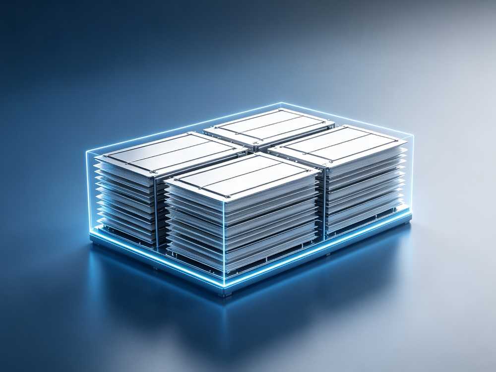
Stack Manufacturing Line
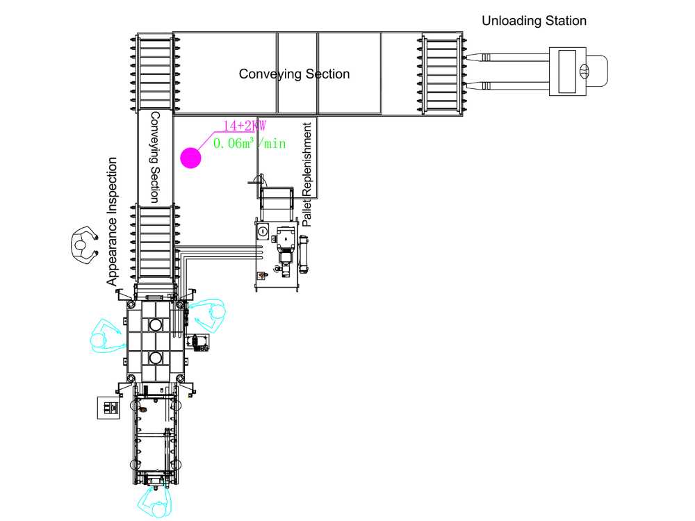
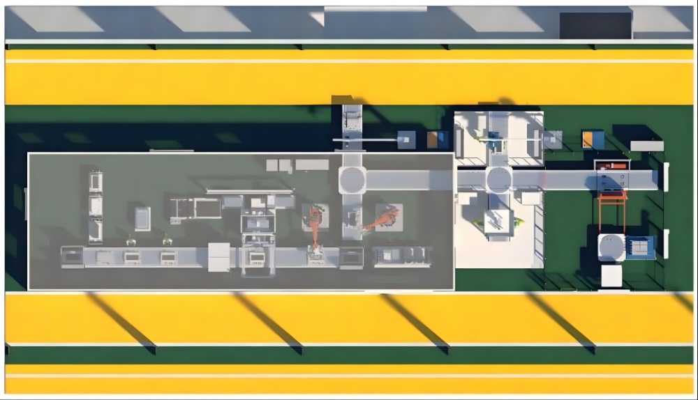
The production line can be used for the assembly and production of flow battery stacks, including a full set of production processes, such as material pretreatment, stacking, pressure stacking, stacking flipping and detection. With modular design and flexible assembly, with mechanise and automated production line, which can rapidly expand production capacity according to production needs.
Mechanized production line
Mechanization: With modular design, stacking press,flip is completed by mechanical equipment, the rest of the process need manual and equipment cooperation to complete, which can reduce the physical operation intensity.
High flexibility: It has a high degree of flexibility in small-scale and diversified product production, and can adjust the production line layout according to actual needs.
Low investment: high equipment integration, relatively smaller economic investment.
Fast production: The installation and debugging of the production line is simple and fast, and it is convenient to put into production as soon as possible.
Automated production line
Automation: The use of advanced automation equipment and technology, greatly improve the production efficiency, reduce the use of manpower.
Flexibility: quickly adjust the production process and product types according to market demand to meet the compatible production of flow battery stacks within a certain size.
Digitalization: Automatic collection of production line data, intelligent digital display of stacking line information.
Visualization: production line information tracing, centralized scheduling control, easy to visual production management.
Intelligent: Vision system, manipulator and a variety of sensors cooperate to control the production process.
Electrolyte Production Line
As the "blood" of the all-vanadium redox flow battery (VRFB), vanadium electrolyte is the core material that determines the performance, lifespan, and cost of its energy storage system. Our vanadium electrolyte electrolysis production line, with high purity, long lifespan, and low cost as its core competitive advantages, is dedicated to providing global customers with large-scale, intelligent electrolyte production services. We aim to supply high-performance electrolytes for the global long-duration energy storage market, supporting the energy transition and the achievement of carbon neutrality goals. To date, we have successfully delivered multiple sets of products both domestically and internationally, achieving our capacity targets and ensuring stable operation.
• Intelligent and efficient: Full-process digital control with real-time monitoring of electrolyte and equipment status; capable of interacting with higher-level systems to enable unattended operation.
• Stable performance: Uses stacks specially designed for electrolyte electrolysis, featuring low energy consumption, no leakage, and low risk of sediment formation and flow channel blockage, ensuring stable operation throughout the designed service life.
• Precise control: Based on years of electrolyte production experience, optimized charging control strategies improve electrolysis speed while maintaining high energy efficiency and reducing power losses, enabling simple one-button production setup and operation.
• High scalability: Modular production line design supports customized expansion with an annual capacity ranging from 3,000 to 30,000 m³, adaptable to energy storage projects of different scales.
Process Package for Manufacturing
Drawing on long-term technical R&D accumulation, mass manufacturing capabilities and extensive project implementation experience, ZH Energy offers complete manufacturing process packages for vanadium flow battery stack and electrolyte production lines. The packages include comprehensive technical documentation: process workflows, work instructions, parameter specifications, production drawings and quality control standards.